Why measure surface flatness?
Surface flatness tolerances are defined for many manufactured parts since flatness is crucial for many applications in order to ensure functionality of technical components. With flatness being an essential surface parameter, it influences e.g. the leakage of sealing surfaces on flanges and valve seats. In precision optics where optical polishing is applied, the flatness of e.g. glass substrates, optical mirrors or beam splitters is one of the most important quality indicators. But not only precision mechanics and optical components widely use flatness tolerances. In the electronics industry it is important to know whether the flatness of PCBs is within specified tolerances to ensure electrical connectivity when attaching multiple parts e.g. via soldering process. For surfaces that move relative to each other, surface flatness can also affect noise levels and sound emission of components. Simply put, flatness tolerances widely influence product reliability, functionality and even noise.
Free feasibility study on flatness and form evaluation!
We measure flatness on your demo samples - onsite or online
ISO flatness and how it is calculated
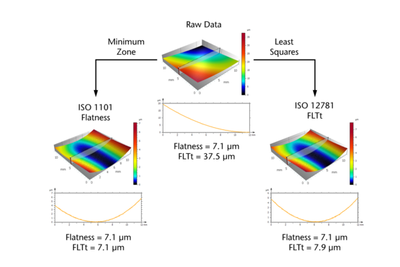
Generally, geometrical flatness in metrology is defined as the difference between two parallel planes throughout all recorded measurement points. However, different ISO standards are available which differ in how to calculate these parallel planes. In order to compare surface flatness measurement results taken with different measurement systems and technologies, it is important to refer to a certain ISO standard. The ISO 1101 standard defines, that the distance between two parallel planes must be as small as possible while including all measurement points. In the ISO 12781, flatness is much more generally defined as distance between the minimum and maximum point of two planes the distance of which depends on previously applied form removals. Regardless of the ISO standard used, it is important to effectively eliminate outliers in the data set to prevent that single spikes dominate the measurement result.
Benefits of optical surface flatness measurement
Flatness measurement is typically conducted using either tactile profilers or in a non-contact way (optically). Tactile measurement systems such as coordinate measurement machines (CMM) are often used for flatness measurement of large parts and where multiple dimensional, geometrical, or positional tolerances shall be characterized. However, CMM measurements often take a long time since it is a point-by-point measurement. Often a bigger point spacing is chosen to save measurement time. However, this approach accepts that local shape deviations will be missed.
